
Roy Hill’s proposed new Berth 3 (SP3) is set to boost iron ore exports with a smarter, more efficient design. Aspec Engineering and Rendel Ingerop were engaged to rework the original concept, introducing a “piggy-back” conveyor and prefabricated wharf jackets with modular deck units.
These innovations will cut construction time, reduce environmental impact, and improve cost efficiency — all while integrating seamlessly with Roy Hill’s existing infrastructure. The 30% detailed design milestone now sets the stage for accurate cost planning and streamlined delivery when the project proceeds.
Jump to: Abstract • Wharf concept • Piggy-back conveyor • Engineering management • Conclusion
Abstract
Port Hedland, Western Australia, the world’s largest bulk commodities port, exports over 600 million tonnes of iron ore annually. HanRoy, the project delivery arm of Hancock Prospecting, is overseeing engineering for a new berth and ship loading facility at Stanley Point, Port Hedland, in a joint venture with Mineral Resources. The plan is to integrate the new infrastructure with existing Roy Hill facilities (Hancock Prospecting holds a 70% stake in Roy Hill). HanRoy engaged Aspec Engineering Pty Ltd and Rendel Ingerop Pty Ltd (Aspec/Rendel) to perform value engineering on a pre-existing design for the proposed new iron ore shipping berth at the Roy Hill Stanley Point export terminal.
The innovative design by Aspec/Rendel featured a “piggy-back” configuration for the overland conveyor and prefabricated jackets for the wharf, leading to significant cost savings. Aspec/Rendel were then tasked with developing the detailed design to a 30% level for accurate cost estimation. The new Berth 3 (SP3) will accommodate cape-sized vessels and be located next to Roy Hill’s existing berths, SP1 and SP2. The infrastructure for SP3 includes a wharf with prefabricated jacket structures and modular deck units, as well as a 3km overland “piggy-back” conveyor that connects the ship loader to new stockyards. These engineering solutions are expected to reduce capital costs by shortening construction time and minimizing the impact on port operations and the environment. Additionally, the project aims to enhance operational efficiency and safety through innovative design features. The prefabricated jackets and modular deck units allow for quicker on-site construction, reducing overall project duration. The piggy-back conveyor design repurposes existing structures, minimizing environmental disruption and further cutting costs. The detailed design phase, reaching 30% completion, ensures precise cost estimation and project planning, setting a strong foundation for the successful execution of the SP3 expansion.
1. Introduction
In February 2022, the Western Australian State Government announced a new allocation of export capacity as part of the Port of Port Hedland development plan. This allocation, intended for the development of Stanley Point Berth 3 (SP3), would be granted to the Hancock Prospecting and Mineral Resources Joint Venture, pending all necessary approvals. Under the Port and Rail Expansion Agreement (PREA) between the joint venture participants, Roy Hill (RH) is responsible for the design, construction, commissioning, and testing of the project. The proposed SP3 Port Expansion includes additional infrastructure within the existing RH port facility, creating an integrated system with an increased production capacity. RH conducted a feasibility study for the expansion, achieving 15% project definition. Subsequently, Aspec/Rendel was engaged to perform value engineering for the marine expansion scope, identifying over $250 million in potential optimizations and savings.
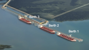
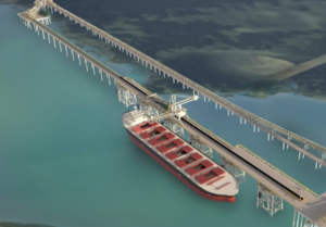
Aspec/Rendel was then engaged to develop the detailed design to a 30% level. This encompassed process and non-process infrastructure for the expansion from the new wharf and tie‐ins to the existing marine infrastructure through to the stockyard feed battery limit, and included civil, structural mechanical, piping, electrical, instrumentation and controls/communications design. The overall layout of Berth 3 relative to existing berths SP1 and SP2 is shown on Figure 1.
2. System description
There will be two outgoing streams. The ship range for Stanley Point Berth 3 will be from 115,000 deadweight tonnes to 206,000 deadweight tonnes.
The scope will include a new piggy-back conveyor on top of the existing overland conveyor CVR 161, which will be called CVR 261. There will be a new transfer deck on the wharf alignment. The new berth conveyor CVR 264 will be on Berth 3 only and will not extend onto Berths 1 and 2. There will be a new access roadway on Berth 3. The Stanley Point Berth 3 will be constructed using prefabricated jackets. Dredging will be required for the berths. A new ship loader at SLD 264 will be included and will be aligned with the new conveyor in a similar configuration to the existing ship loader.
3. Wharf
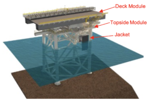
The Aspec/Rendel concept is relatively new to WA Iron Ore ports, using a jacketed wharf instead of the traditional ‘stick build’ method. This design uses marine jackets and modular deck units for faster construction. Each unit, weighing up to 600 tonnes, would be prefabricated off-site and transported by heavy-lift ship.
During installation, jackets (with mud mats prefabricated onto the jackets) are placed in prepared beds on the seafloor. Piles are driven through the jacket legs to anchor them to the seabed and then cut off above the jackets. After installing the jackets, the deck units are positioned and welded together. Aspec/Rendel designed a top module between the jackets and deck units for access platforms and mooring equipment. The shiploader and modular wharf conveyor, matching the deck spacing, will be added after construction. units.
Figure 2 shows a view of the jacket and deck assembly and Figure 3 shows the wharf layout with jackets, deck and shiploader.

The design of the wharf will also include secondary infrastructure required for operational efficiency and safety. It will feature access catwalks between the jackets under the wharf deck to optimise mooring line walking, streamlining the time needed to moor each ship safely. Catwalks are installed prior to the deck modules and facilitate safe access during construction for topside installation. Safety is prioritised with the latest safety screen technology to protect personnel near the mooring hooks against mooring line snapback. The two jackets adjacent to the existing transfer deck will include a large maintenance deck and storm tie-down facility for the shiploader. It also offers a small boat landing facility that enhances operational access to line boats at all tide levels.
By adopting a prefabrication approach to the wharf, overall on-site construction time is reduced. This therefore leads to significant cost savings. Dredging volumes were reduced as far as possible through design of steeper slopes to that originally proposed. Mitigation specified included silt curtain, appropriate dredging speeds and methods.
4. Shiploader SLD 264
Figure 4 shows the existing slewing/luffing type shiploader on Stanley Point Berths 1 and 2.

The plan is to use a similar shiploader on Stanley Point Berth 3. The new shiploader will be confined to operating on Berth 3. The shiploader will have a fixed length boom with a diverter spoon to regulate the trajectory of the iron ore flowing into the ship’s hold. The top part of the shiploader rotates about the base on a slew bearing driven by a pinion system. The boom’s horizontal angle is varied using hydraulic luffing cylinders to suit the ships vertical position which changes due to tide and displacement depth. Material is fed onto the shiploader by means of a travelling tripper integrated with the berth conveyor.
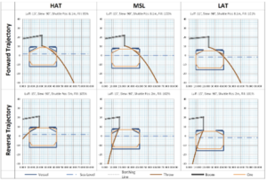
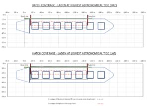
A hatch study was carried out to analyse a ship’s hatch cover openings to determine the adequacy of position and reach of the shiploader. Figure 5 shows the trajectory of material flow into the ship’s hold at various tide levels and the length of travel of the machine required for covering the hatches.
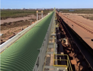
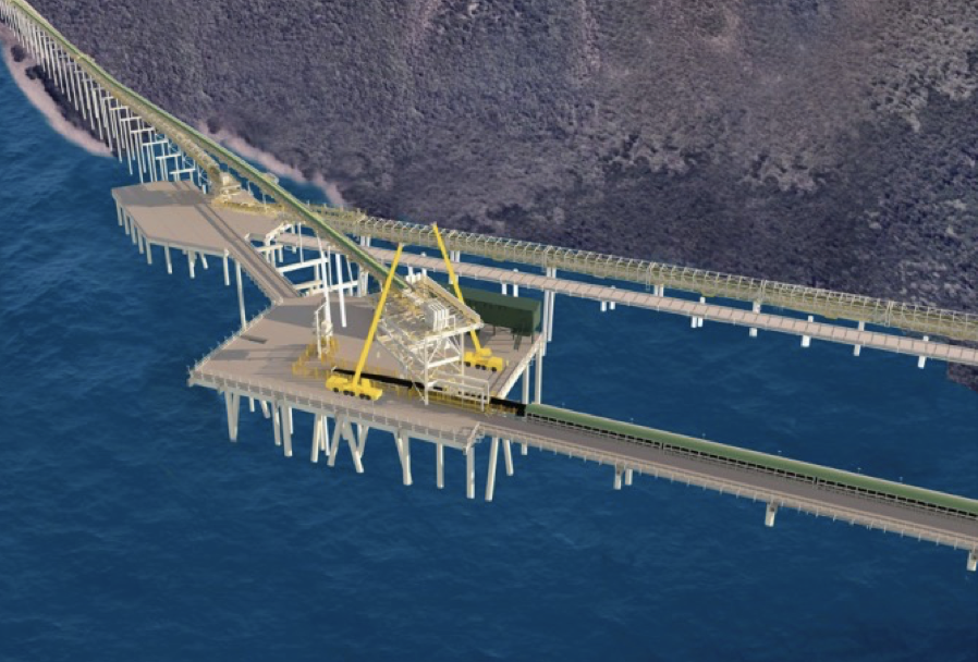
5. Overland Conveyor CV261
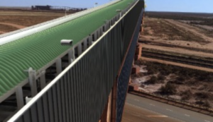
Another key innovation in the SP3 project is the implementation of an overland piggy-back conveyor, a design approach that repurposes the existing overland conveyor structure, eliminating the need to duplicate it over a 3km marine marshland. Overall views of the conveyor arrangement are shown on Figure 6 and Figure 7. This shows the new overland conveyor CVR261 on top of the existing overland conveyor CVR161 eliminating the need for duplication of the support structures over marshland, thus resulting in considerable cost saving and a much better environmental outcome than constructing a separate additional conveyor structure. A key consideration for the design was the additional windage area due to the “piggy-back” conveyor in a region D cyclonic location. To obtain additional assurance about the forces involved, the client commissioned wind tunnel tests to determine the drag coefficients and this was used in the design.
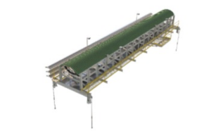
The new piggy-back conveyor will comprise truss modules fabricated to accommodate mechanical and electrical equipment, walkways, guarding and instrumentation as shown on Figure 8. These modules are supported by existing conveyor trusses at four points and secured with tie-rods to the existing headstocks. In addition, the design of the piggy-back conveyor also incorporates a full-width deck into the new conveyor modules, effectively segregating the upper and lower work areas to ensure the safety of all operational maintenance personnel.

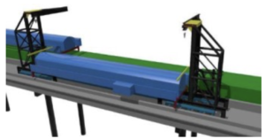
The installation of this piggy-back conveyor will be performed using crane arms on self-propelled mobile transporters (SPMTs) as shown diagrammatically on Figure 9, allowing for rapid assembly from the existing roadway. Since only a few modifications are required on-site, the installation process is streamlined, ensuring minimal disruption to operations.
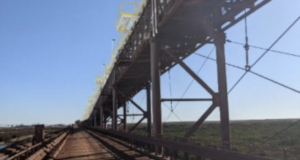
The seaward head end section of the existing conveyor rises in elevation to the transfer tower as shown on Figure 10, so in this area it is not possible to use the transporter/erector. Hence craneage and falsework will be required to erect the modules.
Where the conveyor crosses the existing road, truss spans as shown on Figure 11 are greater than the standard module length of 24 m and the supports are skewed to suit the road alignment. The modules in this area will be non-standard and will potentially require to be lifted in by cranes at ground level.
The CV262 conveyor spans across the drive station for the existing CV161 conveyor as shown on Figure 12. The drive station is located midway on the conveyor alignment. Because of the constraint of the conveyor below CV261 it was necessary to have a head end drive on the new conveyor.

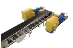
Figure 13 shows the head end drive arrangement with two 2-megawatt drive systems, one each side of the conveyor onto the head pulley. The drives, comprising gearbox, coupling and electric motor are standardized with other drives used in the overall facility.
A gravity take-up is positioned at the tail end of CVR261 conveyor as shown on Figure 14. It has a horizontal trolley and a reeved system to a tower, within which the counterweights travel to maintain tension on the conveyor belt.
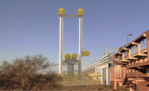
Figure 15 shows the head end of the CVR261 overland conveyor “Piggy-back” configuration above CVR161. The conveyor feeds onto the wharf conveyor CVR264 through a transfer chute. The head end of the conveyor is supported by a transfer tower which sits on the transfer deck. The piles for the transfer deck are to be installed individually with the deck placed on top of these. The deck will be constructed of prefabricated modules built off site and transported to the location by heavy lift ship.
The new conveyor spans over the head end of the existing overland conveyor CVR161 which requires modifications to the existing transfer tower.
6. Berth Conveyor CVR264
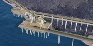
Figure 16 is a closer view of Stanley Point Berth 3 showing the conveyor in relation to the berth and access jetty.
The new berth conveyor CVR264 is fed from the overland conveyor CVR261 at the transfer station. It has a design throughput rate of 15,400 tonnes per hour. Other features include a 2000mm Wide Belt with 5.25 m/s Belt Speed.
There is a 2000 kW Drive at the head end to power the conveyor. The moving tripper which feeds the shiploader is an integral part of the berth conveyor using bend pulleys to divert the belt through the structure. Other features of the conveyor are the belt wash station near the head end and the gravity take-up at the tail end with a horizontal sliding arrangement for the tail pulley.
The approach jetty piles will be individually driven with a headstock attached on site. The road deck and conveyor trusses will be manufactured off site as modules and lifted in on site. The intention is for the conveyor truss modules to be fully fitted out off site.
7. Maintenance Access
Maintenance access was a major consideration in the layout of the transfer deck as mobile cranes are required to remove the drives and chute components during programmed shutdowns. The electrical switchroom is also positioned on the transfer deck so clearances and turning circles needed to be allowed for.
Aspec/Rendel carried out crane lift studies to confirm the feasibility of the layout as shown in Figure 17 below.
8. Engineering Management
The design team consisting of 30-50 personnel was resourced across four offices. Rendel’s offices in London and Sydney designed the marine jackets and deck units, with Aspec’s offices in Brisbane and Perth responsible for the materials handling structures, conveyors and shiploader. The scope also included an electrical engineering design component which was completed by Engenuity Solutions who worked with Aspec/Rendel and the Roy Hill team to align these designs with the existing site architecture and equipment.
9. Conclusion
In conclusion, the innovative design and engineering solutions implemented in the Stanley Point Berth 3 (SP3) expansion project at Port Hedland demonstrate significant advancements in cost efficiency, environmental sustainability, and operational safety. The use of prefabricated jackets and modular deck units, along with the piggy-back conveyor system, not only reduces construction time and costs but also minimizes environmental disruption. These measures, combined with detailed planning and value engineering, ensure that the SP3 expansion will enhance the port’s capacity and operational efficiency, setting a new standard for future port infrastructure projects.
Need bulk-handling engineering advice?
Talk to our team about life-extension, upgrades or compliance audits.