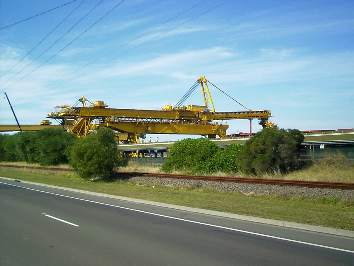
The specification and design audit of rail-mounted machines such as shiploaders, stackers and reclaimers requires careful consideration of how the equipment will operate throughout its service life.
Aspec Engineering has extensive experience in bulk materials handling machine design audit and specification. In this article, Richard Morgan looks at the key considerations when procuring new equipment, including machine configuration, technical specifications, structural and mechanical design auditing, and issues that can arise during construction and commissioning.
Jump to: Introduction • Developing Machine Configuration • Specifications for New Machines • Structural Design Audit • Mechanical Design Audit • Issues During Construction/Commissioning
Introduction
Materials handling machines for the mining, metallurgical and associated industries have shown failure rates higher than standard static structures. Under workplace health and safety legislation, owners and operators of such equipment have significant responsibilities for risk management of the machines. There is a strong need for owners, operators’ designers and manufacturers to adopt a pro-active approach to risk management throughout the asset lifecycle including procurement, design, manufacture, installation and ongoing asset management and maintenance.
As well as the need for new machines for extension of export terminals and mines, many installations have equipment at the end of their original design life and in normal circumstances would carry out a mid-life refurbishment to allow the equipment life to be extended. However, due to the strong demand for commodity exports and high prices, downtime is critical and machine replacement is often found to be a more cost-effective option to refurbishment, hence many owners are adopting this option.
When procuring new bulk materials handling machines, the following stages need to be considered:
- Determination of configuration
- Specification and procurement
- Design Audit
- Issues During Construction
Developing Machine Configuration
Determination of a suitable configuration of a machine and performance parameters such as outreach, throughput rate, utilisation, design life etc is intimately linked to the business objectives and process/quality requirements for the materials being handled. Future trends in business, shipping etc are also important and allowance for flexibility and responsiveness to the market may need to be considered in the equipment selection and specification.
Features of different types of materials handling equipment are described in this section.
Shiploaders
Shiploader Configuration
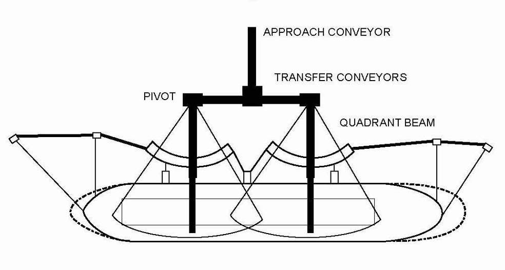
The length of the berth is determined by the largest ship expected and to a lesser extent by the type of shiploader selected. Some of the most frequently used types of shiploaders are shown diagrammatically in Figures 1, 2 and 3 below. In the case of a long travelling shiploader, the travel length should generally be equal to the distance between extreme hatches on the largest ship using the berth to avoid the need to move the ship along the berth (termed warping).
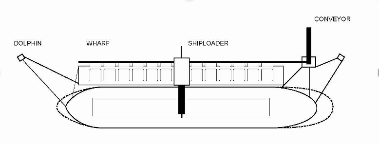
The use of radial loaders or linear loaders can lead to a reduction in berth length. Both linear and radial type shiploaders pivot about a central point, the former having a longitudinal runway beam adjacent to the berth and the latter having a quadrant beam on a radius. Single shiploaders of this type are limited to ships of maximum size 100,000 DWT and 65,000 DWT respectively. For larger ships a long travelling type shiploader or dual quadrant (radial) shiploader system is required.
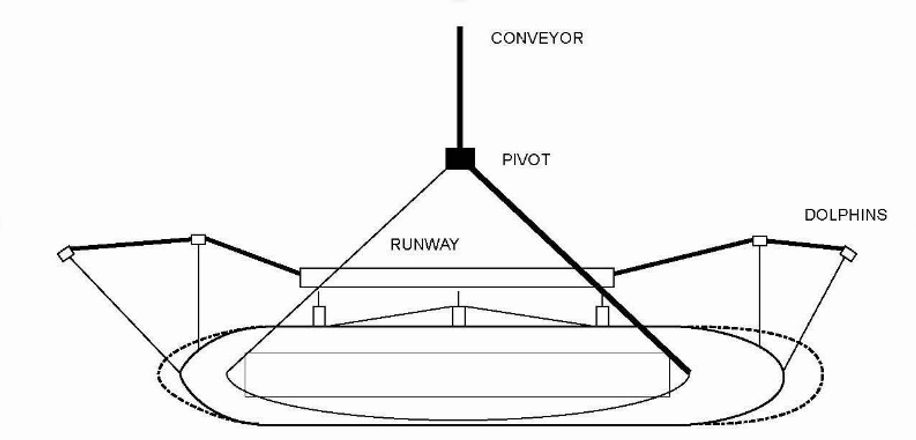
A major advantage of linear and radial type shiploaders is the ability to minimise dust and spillage as the transfer from the approach conveyor system to the shiploader is at a single point, whereas a long travelling shiploader requires a wharf conveyor and tripper which increases the potential for dust and spillage.
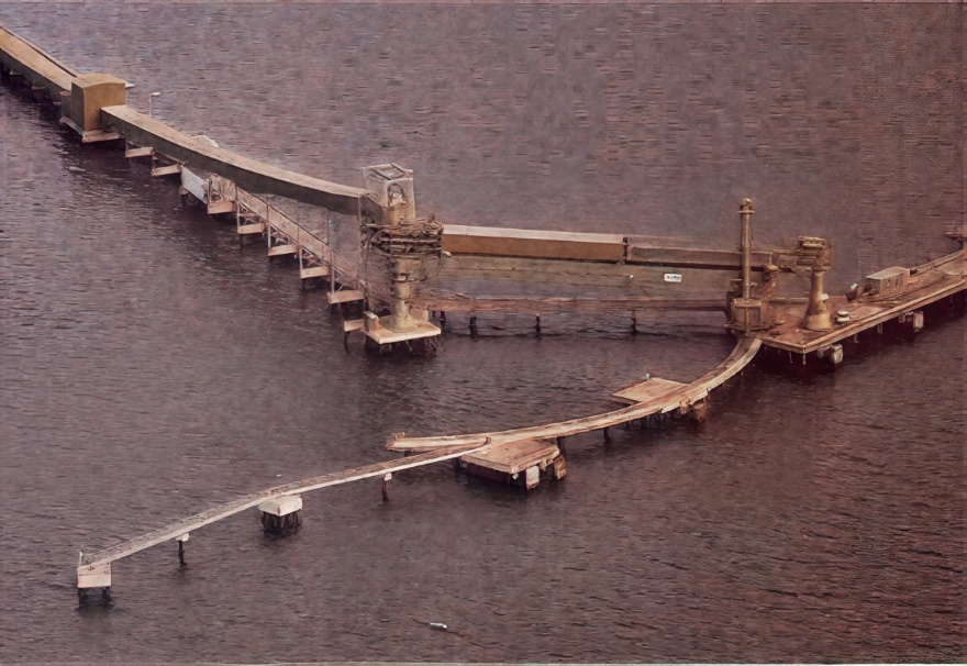
Shiploaders – Bridge Type
Bridge type shiploaders have a large travelling bridge spanning from the seaward rail to a second rail or pivot point located on the land or some distance behind the berth on a structure where the berth is at sea. A shuttling trolley system, which supports the boom, tower, and luffing winch system travels along the bridge.
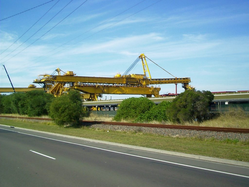
Bridge shiploaders may be long travelling, radial or linear types. These shiploaders tend to be large and relatively heavy compared to portal gantry and portal slewing types. Metal fatigue in the bridge girder and at the boom head due to chute rotations are common issues with this type of shiploader. For the long travelling bridge type, skew control is very important to avoid derailment or other major damage.
Shiploaders – Portal Gantry Type
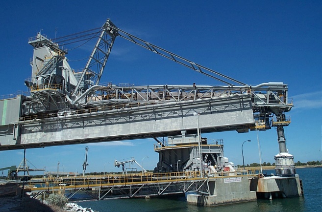
Long travelling shiploaders with narrow wheelbases up to approximately 20 metres often have a portal structure spanning the rails and a fixed boom gantry set at 90 degrees to the rail track. The boom conveyor shiploading chute shuttles in and out to load the hatches and due to geometry, there are limitations on the length of inboard travel of the shuttle. The shuttle mechanism may vary the length of the boom as in figure 7 or the boom may be of fixed length with the shuttle within the boom as in figure 8.
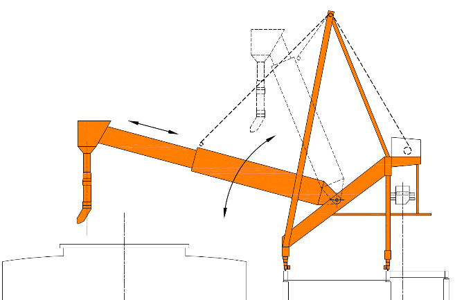
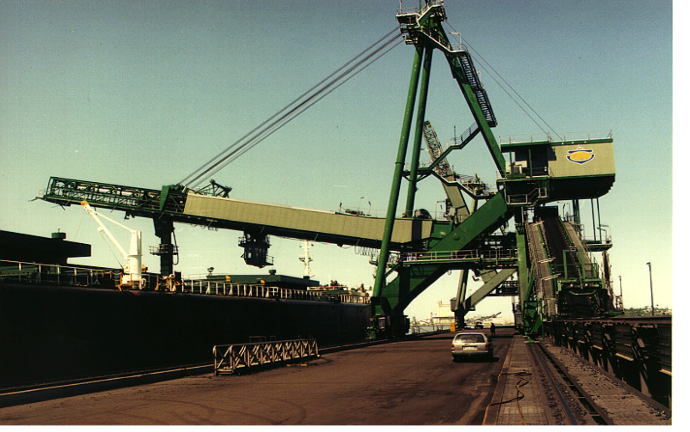
This type of shiploader is best suited to loading ships when ship sizes do not vary too much. Such shiploaders have a roped boom luffing system with winch as the boom must luff up to vertical or near vertical to allow ships to berth. Thus, these machines are not balanced and have a large variation in overturning moment depending on the configuration.
Shiploaders – Portal Slewing Type
The portal slewing type shiploader is suitable for ships without masts and cargo gear. Trimming of hatches is accomplished by a combination of slewing and long travel motions. This gives some limitations, so this type of machine tends to be used for dedicated ships.
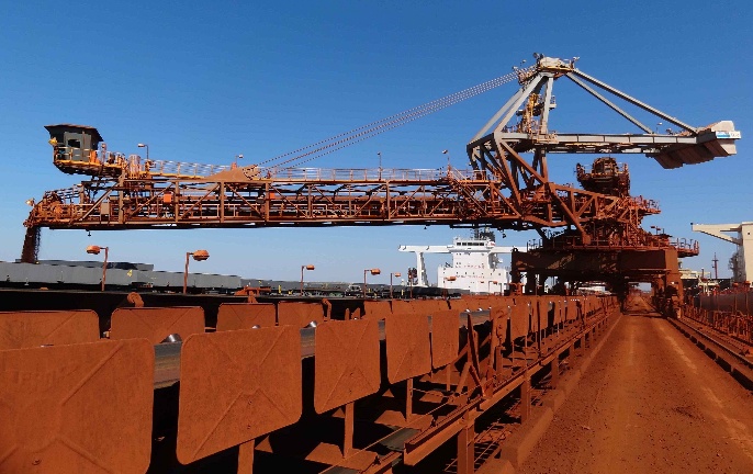
Shiploaders – Portal Slewing/Shuttling
The portal slewing and shuttling type shiploader allows for greater flexibility in loading different ship types than the portal slewing type. Both these types of machines can be balanced configuration as the ability to slew allows the boom to be stored behind the quay line for parking and ship berthing without the need to luff up to vertical as for the long travelling portal type.
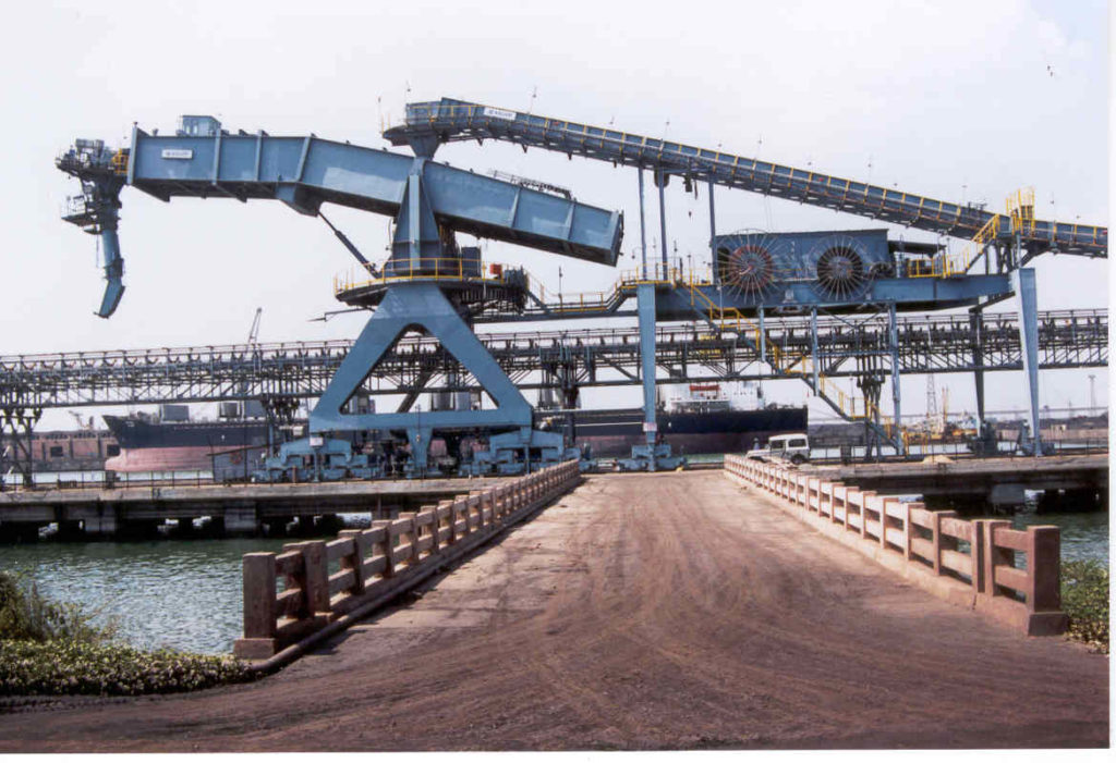
Reclaimers and Stacker Reclaimers
Boom type bucketwheel reclaimers and stacker reclaimers are highly loaded structures which are generally very sensitive to changes in balance. Changes in weight and weight distribution need to be carefully monitored and controlled. The repetitive loading due to the bucketwheel motion requires consideration for metal fatigue of the structure and slew bearing.
Figure 11 shows a stacker reclaimer used for handling coal. This type of machine has a tripper which must be retracted on a linkage arm to slew from one side of the stockpile to the other or to reclaim in certain quadrants. The reclaimer has a tubular boom and fixed counterweight, which pivots as a total assembly above the slew deck.
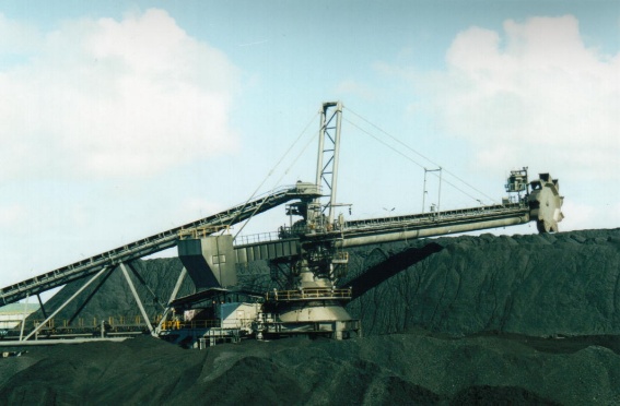
Figure 12 shows a “J” frame configuration stacker reclaimer. This machine also has a retractable link to allow slewing on each side of the rail line and reclaiming in 4 quarters. The “J” frame machine is articulated with two pivot points, one for the boom and one for the counterweight.
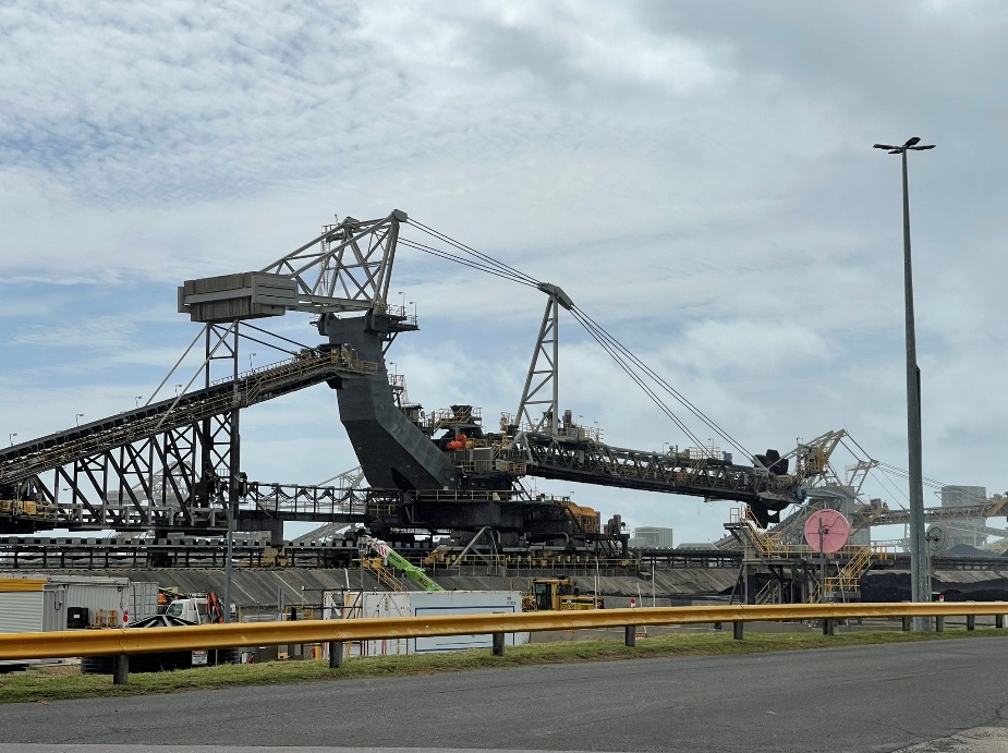
A “C” frame configuration is used where there is insufficient room to have an extendible towing link on the tripper. Such machines can slew to both sides of the rail tracks without the need to extend the tripper.
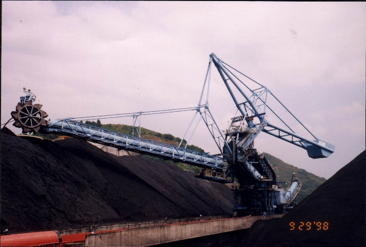
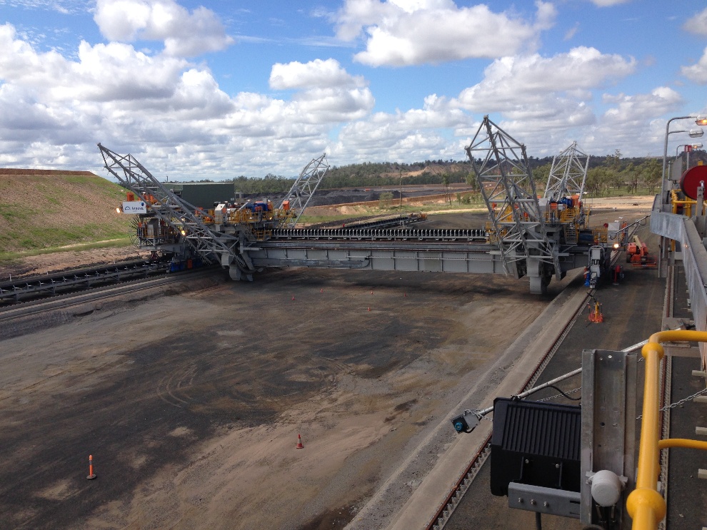
Figure 14 shows a bridge reclaimer of the bucker wheel type used for reclaiming on the face of a blended stockpile. Note the “rakes” which are used to loosen material on the active face.
Stackers
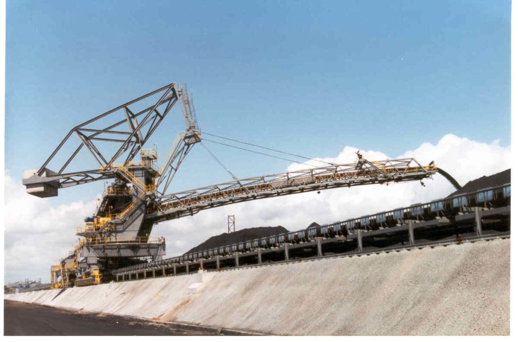
Stackers are generally required to predominately long travel with limited slewing motions to lay the stockpiles for subsequent reclaiming by a slewing or bridge type reclaimers. Figure 15 shows an older stacker, which is luffed by means of a winch system. On most modern machines luffing is carried out by means of hydraulic cylinders.
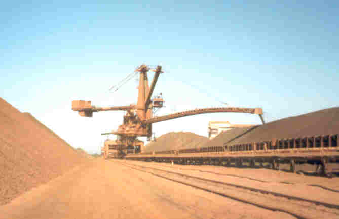
Stackers with longer spans are often articulated to provide less variation in load during the luffing motion.
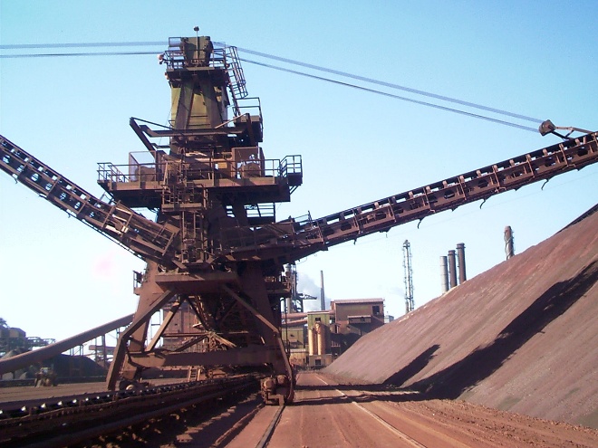
Fixed “Bat Wing” stackers can be used where the stockpile system is very regular. These are often used in conjunction with a bridge reclaimer.
Specifications for New Machines
The standard method for procuring bulk materials handling machines is a design and construct contract with the contractor having responsibility for design, manufacture, supply and installation. In some cases, the contracts may be split to suit the logistics of construction or for commercial reasons. However, if this is contemplated, care should be taken to keep the responsibility for final performance with one party.
The specification for the machine should cover design, material and quality requirements for manufacture and installation, commissioning and hand over to operations, provision of spare parts and requirements for ongoing maintenance. The specification needs to be written to ensure that the configuration and performance parameters upon which the requirements for the machine were determined can be met realistically in practice.
Specification of the design requires a good knowledge of the design standards; their limitations and interpretations of the design standards commonly used within the industry. Industry experts should be consulted to ensure that problems commonly encountered on equipment of this type are not repeated should review the specification. The operators and maintainers of the plant have a large influence on the ongoing safe performance of the machine and should also be involved in review of the specification.
AS4324.1 Mobile equipment for continuous handling of bulk materials – General requirements for the design of steel structures was introduced in 1995 in response to failures of bulk materials handling machines within Australia and has been updated in 2017 and 2025. This Standard specifies general requirements, design loads and specific requirements for structures of mobile equipment for continuous handling of bulk materials, including appliances and machines that are intended to carry out similar functions (e.g. excavators, stackers, reclaimers, ship loaders, ship unloaders). Appendix B in the standard specifies relevant information to be supplied in the technical specification for procurement of a machine.
AS4324.1 calls up other Australian Standards such as AS1170.2 for Wind Loads, AS3990 for permissible stress steel design and AS4100 for limit states steel design. AS4324.1 requires that fatigue design be carried out to AS4100.
The International Standards Organisation has published design standards bulk materials handling machines such as stackers, reclaimers, ship loaders and ship unloaders (ISO5049.1) ISO5049.1 has been widely used internationally; however, its use has been discontinued in Australia since the introduction of AS4324.1 in 1995. Steel design requirements for strength and fatigue and wind loading are covered in ISO5049.1. However, these vary from Australian Standard requirements in several respects.
Some of the issues commonly encountered in developing the machine specification are described in the table below.
| Subject | Comment |
| Support System | It is desirable to have a 3-point support system so that the loads on each wheel group are statically determinate. In this way the wheel loads do not vary significantly with foundation settlement or deflection of the machine or support structure. |
| Slewing Capabilities | Where the machine has slewing motions and is required to load on each side of the rail, a “C” frame or extendable link is required. |
| Trenching Mode | The trenching mode of reclaim digging with a reclaimer increases the likelihood of an end on collision. Also, calculation of fatigue loads for the trenching mode is not specifically covered in AS4324.1. |
| Anti-Collision | Prevention of overload during trenching is difficult as the overload may occur before the system can react. |
| Design Approach | Plate elements should be used to analyse the machine portal and slew deck. The analysis should suitably detailed to identify buckling modes in the portal and slew deck plates and frame elements in the superstructure. |
| Design Standards | Refer to previous section for comments. |
| Fatigue | AS3990 should not be used for fatigue design as the approach is outdated and nonconservative. Use of 0.7 factor for non-redundant load paths and inaccessible areas for inspection as per AS4100 should be mentioned |
| Stability | Careful consideration needs to be given in the specification for the grounding condition. Where partial grounding (A2) is allowed particular attention needs to be given to overload protection. |
| Service Life | The maximum practical design life for mechanical components is usually 10 years in accordance with the classifications in the crane standard AS1418. After this time, they need to be refurbished or replaced. |
| Rail Section | Rail section type should be specified. |
| Wheel Loads | It is important to stipulate maximum wheel loads as there are practical restrictions to the load that the rail mounting system can take. |
| Bucket Wheel Shaft | The Bucket wheel shaft in a reclaimer is critical to the structural integrity, however it is often considered as a mechanical item and not included in the structural audit. |
| Slew Bearing Maintenance | Accurate measurement of jacking loads should be carried out during the demonstration of the slew bearing change-out for the purpose of verifying the COG of the superstructure. |
| Slew Drives and Ring Gear | Consideration needs to be given to drive locations. If drives are too close together pinion loads and horizontal deflections on the ring may be magnified. This also can affect the natural frequency in the torsional mode. |
| Extension System on Stackers | Due to the length, vibration of the extension beam can be a concern if the beam stiffness is not appropriately chosen. |
| Boom Conveyor | Under-slung drive arrangement may be preferable to a tail drive. |
| Cabin Support System | Pivot point should allow the cabin to hang vertically under self-weight at different boom angles rather than a system which requires active hydraulics to keep the cabin level. |
| Maximum Slenderness Ratios | Max Slenderness Ration should be 180 for compression members. |
| Counterweights | Counterweight design should allow for balancing to be carried out. This is typically with steel plates. |
| Main Switch room | Switch room must be designed to meet structural criteria. Off the shelf prefabricated switch rooms need to be checked thoroughly. |
Structural Design Audit
AS 4324.1 Appendix K gives guidance for engagement of a design audit engineer, sometimes termed proof engineer, for structural auditing. The process involves design auditing and certification by an independent 3rd party engineering consultant. This may be by means of independent calculations or in some cases by checking and reviewing the original design calculations and computer analyses. Independent calculations are the preferred method. In conjunction with the design audit, it is desirable to hold one or more facilitated workshops with key staff from the designer, operator, maintainer and proof audit-engineering consultant present.
The audit engineer should ideally be engaged before the specification for the machine is finalised to allow for a review by the proof engineer prior to issue. Involvement of the audit engineer by the client in the tender review process is also desirable.
AS4324.1 is a standard for the design of steel structures for continuous materials handling machines. When applying Appendix K to the standard for a design audit, the question has arisen as to who is suitably qualified to carry out the role of design audit engineer. The standard nominates this as follows:
Design audit engineer—a suitably qualified engineer who undertakes independent checks of the design (also known as a proof engineer).
However, this definition does not nominate the required qualifications or engineering discipline. As this is a structural standard, the preference is that this role should be carried out by a Structural Engineer.
National Professional Engineers Register (NPER) competencies for Structural Engineers were developed by the Structural College of Engineers Australia. The base qualification accepted by the College has typically been a 4-year Structural or Civil Engineering bachelor’s degree. There are few purely Structural Engineering degrees so most Structural Engineers tend to have a Civil Engineering degree. However, the Structural College has in some case recognised that persons with a Mechanical Engineering base degree may be eligible for registration as a Structural Engineer. The main emphasis in selecting a design audit engineer should be to select a consultant with strong technical qualifications and considerable experience in the field. In some jurisdictions, registration of engineers may also apply.
Mechanical Design Audit
Although not included in Appendix K of AS4324.1, a mechanical design audit of the machine is also desirable. The mechanical design audit should involve review of the machine designer’s selection of mechanical equipment as well as review of manufacturer’s data and specifications to assess the validity of the related loading assumptions and compliance with the technical specification. The following equipment should normally be included in the mechanical design audit:
- Long Travel Drives
- Slew Drives
- Slew Bearing
- Boom Conveyor Drive
- Luff Hydraulics
- Conveyors
- Wheels
- Bucketwheel Shaft (if applicable)
- Bucketwheel Drive (if applicable)
- Shuttle (if applicable)
- Winches (if applicable)
As a minimum, the mechanical assessment should cover the design and selection of mechanical components producing loads affecting the structural design of the machine.
Issues During Construction/Commissioning
The following relates some of the problems encountered on projects and key learnings:
Transmission of Information
During a complex design and construct conduct, many versions of drawings and documentation are transmitted and received. Systematic registration and control of this data is essential to avoid re-work and inefficiencies in the auditing process.
Electrical/Mechanical Protective Devices
Protective or load limiting devices in the electrical, control, mechanical and hydraulic systems are very important in determining the load imposed on a machine. This is an area which requires close attention both in the design phase and on site to ensure that the devices as installed perform the correct function.
Weight Control
The final weight of a machine is often greater than that advised at time of tender even when the supplier has carried out an upfront concept design phase. Due to contractual pressures during the contract, weight measurement of components leaving the fabricator shop may be overlooked. It is strongly recommended that weight control be policed strictly through the contract.
Fabrication Issues
Issues may arise during the fabrication stage (particularly on large items that are fabricated overseas). Experience has shown that major issues may be avoided by having a rigorous inspection regime in place and requiring proper documentation.
Visits should be made to overseas fabrication works to prepare a consignment approval report prior to major fabrication items being released for transport to site. This should include a physical inspection and sighting of Material Data Records (MDR’s), NDT Reports, dimensional inspection reports etc., in accordance with the contract specification.
Shock and Vibration
During the commissioning phase care needs to be taken in testing the emergency stops on the machine. When stopping is via the braking system via controlled electrical stopping severe forces can be imparted into the structure if the brakes or rail clamps are not adjusted correctly and are applied too quickly during power deactivation of the electrical system.
Machine Specification & Design Auditing
Aspec Engineering provides specialist engineering support for the specification and independent design auditing of bulk materials handling machines, including shiploaders, stackers and reclaimers.
To discuss machine specification or design auditing requirements for your project, contact our team.

Richard Morgan is a Structural Engineer and Senior Advisor to Aspec Engineering with extensive experience in bulk materials handling and ports. He is chairman of Australian Standards Committee ME43 for materials handling machines. He is a Chartered Professional Engineer.